Specification of machine guard glazing: standards, tests, field of view, installation
Guide for industrial users: requirements, relevant standards, test methods, field-of-view criteria, installation and service life of machine guard glazing.
Term and classification of machine guard glazing
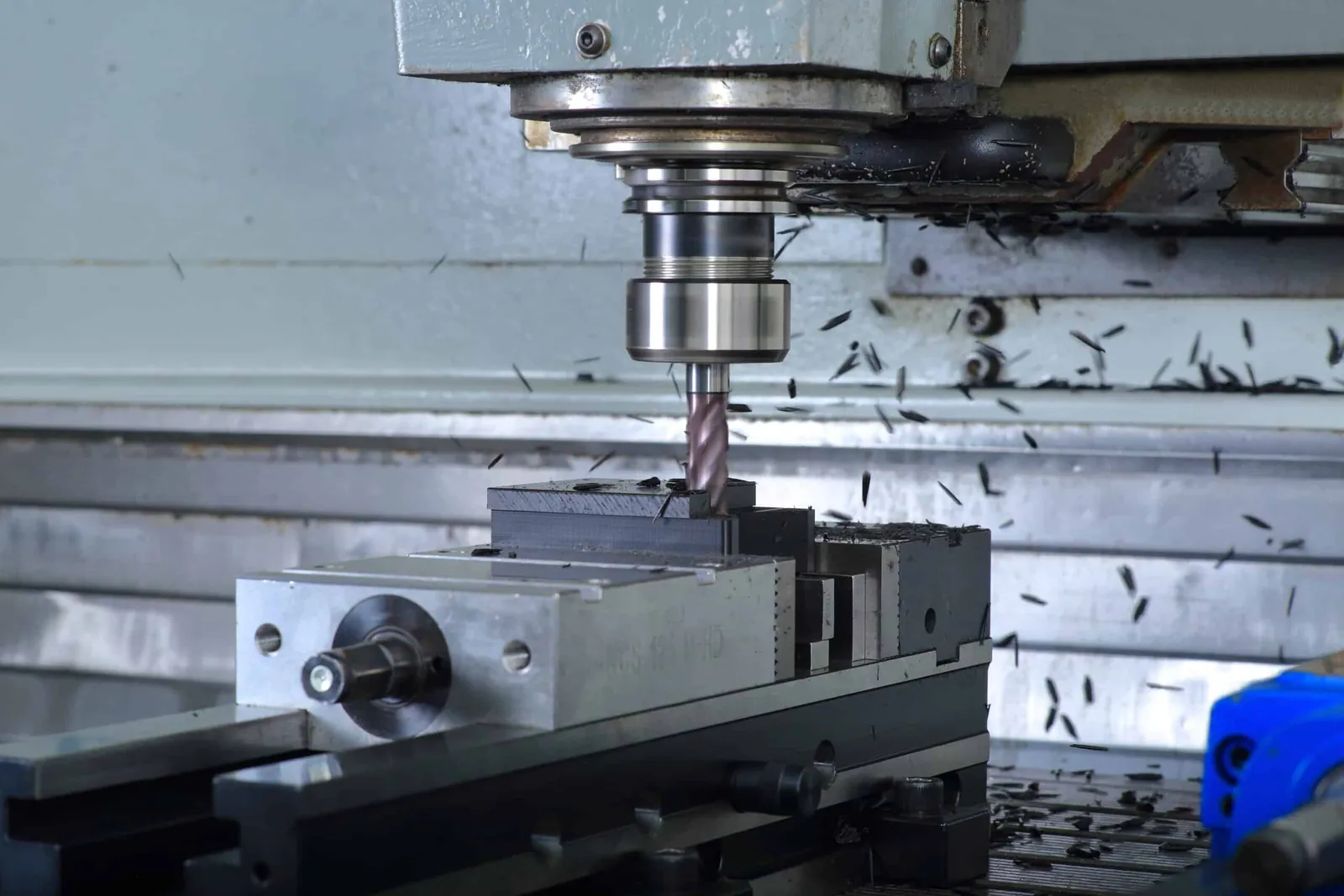
Machine guard glazing are transparent elements within separating protective devices. They enable process observation and at the same time serve to retain chips, tool breakage fragments and cooling lubricants. In the specification, protective function, optical quality and media resistance must be considered as equally important. The required scope of performance is derived from the risk assessment of the specific machine and comprises the combination of material, construction, fastening, sealing system and maintenance concept.
Standards and risk assessment
Relevant standards and directives
For the design and testing of protective devices on machine tools and other installations, internationally harmonised safety standards are authoritative. They define basic requirements for separating protective devices, procedures for risk assessment, testing and verification principles as well as marking. A coherent consideration of standards, conformity and documentation is provided by the overview of standards and approvals for engineering plastics. The specific selection of the standards to be applied is always machine- and process-specific.
Derivation of performance requirements
The risk assessment defines the necessary resistance to occurring hazards. These include the retention of potential projectile fragments, resistance to cooling lubricants and cleaning chemicals, temperature and pressure loads in the working area as well as requirements for visibility and ergonomics. From these points, characteristic values such as the construction of the glazing, minimum thickness per layer, impact resistance, permissible deformation, optical limit values and inspection intervals are derived. The resulting requirements must be clearly recorded in the drawing, specification document and test and acceptance plan.
Material selection and optical characteristic values
Material options and laminate constructions
In practice, various materials and composite constructions are used. Polycarbonate is an established core material due to its high impact strength, often in combination with glass or hard layers. A material basis for polycarbonate is provided by the material page Polycarbonate. Glass-based composites are also used when increased surface hardness and chemical resistance are required. For material selection and the weighing up of polycarbonate, glass and possible laminates, the article on material selection for viewing windows in machines provides reliable guidelines.
Composite constructions combine the advantages of the individual materials. Typical goals are an impact-resistant core layer, hard and chemical-resistant cover layers, UV protection as well as an exchangeable sacrificial layer on the inside. The final construction is chosen so that the required retention function, the optical quality and the resistance to media over the life cycle are reliably achieved.
Optical specifications
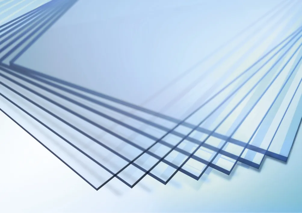
For process observation, transparency and low optical distortion are central. Clear requirements for light transmission, haze, permissible inclusions, deformations in the viewing area and a defined usable viewing zone have proven themselves in specifications. A precise definition reduces later discussions at acceptance. Fundamentals on transparent materials and their optical properties can be found under transparent engineering plastics.
Surface coatings and antistatic properties
Hard coatings increase scratch resistance and cleaning resistance. The selection and suitability of such layers, in particular on polycarbonate, are discussed in practical terms in the article on hard-coated polycarbonate sheets as well as in the comparison of relevant hard coatings. Depending on the process environment, an antistatic finish can be helpful in order to reduce particle adhesion and fog formation on the surface. The specification should take into account the effect of coatings on optics, cleaning chemicals and repairability.
Tests and verification
Impact and penetration resistance
The core function of the protective glazing is the safe retention of fragments and chips. For this purpose, verification of impact and penetration resistance is required. These are usually carried out as component tests on representative test specimens or samples with production-identical boundary conditions. Projectiles, impact points, energy and number of hits are derived from the risk assessment and applicable standards. In addition, deformation limits and the integrity of fastening and sealing must be verified. A methodical introduction to the planning of such tests is provided by the article Plastics testing as well as the in-depth article on reliable test results.
Ageing and media resistance
Machine guard glazing are exposed to cooling lubricants, cleaners and temperature changes over years. The resistance of the overall construction including coatings, intermediate layers and seals must therefore be verified. Realistic ageing pre-treatment before mechanical testing is recommended. Fundamentals on interactions of chemicals with plastics can be found in the article Chemical resistance and on time-dependent change effects in Ageing processes in plastics.
Scratch resistance, abrasion and cleaning
Scratch resistance and abrasion behaviour influence the visibility quality during operation. The selection of suitable hard coatings as well as clear cleaning approvals are required in order to limit optical degradation. Proven care and cleaning rules are summarised in the article on cleaning and care of transparent plastic glazing. For assessing surface hardness, standardised hardness testing methods can be used, as described in the overview of hardness testing methods for plastics.
Field of view requirements and ergonomics
Arrangement and size of the viewing window
The viewing zone should make the relevant working area perceptible without turning the head or body. In the specification, the position, size and height of the viewing opening, the usable viewing area as well as permissible frame overlaps are defined. Glare from room or machine lighting is to be avoided. Coordinated machine lighting and a low-reflection orientation increase the readability of the process and safety.
Condensation, fog and particles
Cooling lubricants, aerosols and temperature differences frequently lead to fog or droplet formation. Measures include suitable air guidance, antifog finishes, a coating adapted to the medium or targeted heating of the viewing area. Relevant cleaning and approval lists of the media used should be named in the specification. In addition, a look at material-related aspects in application in mechanical and plant engineering is worthwhile.
Design, assembly and sealing concepts
Frame, clamping and load path
The mechanical integration must ensure the load path from the viewing window into the machine. Frames and clamping strips distribute forces evenly, avoid local stress peaks and protect edges. Fastening spacings, clamping lengths and corner radii are designed in accordance with the loads to be expected. Particular attention must be paid to possible interactions between deformation of the viewing window and sealing contact pressure, so that tightness is maintained even under load.
Seals and chemical compatibility
Seals must be compatible with cooling lubricants and cleaners and must not attack the glazing material. Plasticiser migration and stress cracking must also be taken into account in the design. The selection is based on media lists and temperature profiles. A supplementary look at the chemical resistance of the materials involved helps to identify risks at an early stage. Drainage and drip edges reduce standing media and extend the service life.
Exchangeable inner sheets and protective covers
In practice-oriented designs, the stressed inner side is frequently protected by an exchangeable sacrificial layer. This solution preserves the optical quality of the main composite for longer and simplifies maintenance and replacement. For this purpose, the specification defines fastening, sealing concept, permitted materials and maximum thickness, so that the protective effect of the overall construction is not impaired.
Service life, inspection and replacement criteria
Inspection plan and documentation
A defined inspection plan is part of the specification. It describes visual inspections for scratches, clouding, cracks, delaminations, coating detachments and leaks. In addition, cleaning approvals, test cycles, permissible limit states and the documentation of the findings are specified. Knowledge of fundamental ageing processes of plastics supports the definition of sensible cycles.
Replacement criteria
The replacement criteria result from the protective function and the required visibility quality. Typical triggers are visible cracks, structural damage, significant optical clouding, non-removable coating defects or damaged sealing edges. The time and procedure of replacement are described including marking and traceability. For maintaining visibility quality, careful cleaning processes are decisive, as explained under cleaning and care.
Documentation, marking and traceability
The technical documentation comprises drawings, bills of materials, specification sheets, test results, approvals and maintenance specifications. Recommended details on the component are material and construction marking, manufacturer or supplier identification, production or batch code, date code, acceptance or test verification and details of the permissible period of use, where provided. A clear marking of the usable viewing zone prevents misinterpretations at acceptance and service.
Practical checklist for the specification
- Carry out a risk assessment and derive the required retention function from it.
- Select material and laminate construction with a view to impact strength, optics, chemicals and temperature.
- Define the optical specification, including usable viewing zone, transmission and haze.
- Define coatings, document cleaning and media approvals.
- Plan impact and deformation verification as a component test, including ageing pre-treatment.
- Design the assembly concept with clamping lengths, corner radii, sealing system, drainage and load path.
- Take into account ergonomic field of view requirements, lighting and minimisation of reflection.
- Specify inspection and replacement criteria, ensure marking and traceability.
- Attach the test and acceptance plan and define the scope of documentation.
Frequently asked questions
Which materials are suitable for machine guard glazing in machine tool construction?
In practice, polycarbonate, glass and composite constructions are frequently used. Polycarbonate offers high impact strength, glass convinces in terms of surface hardness and chemical resistance. Composites combine these properties depending on the requirement.
Which tests are customary for verification?
Component tests for impact and penetration resistance are customary, where applicable after ageing pre-treatment. In addition, optical characteristic values, scratch resistance, tightness and the integrity of frame and seal are tested.
How are the field of view and optical quality sensibly specified?
Define a usable viewing zone with limit values for transmission, haze, permissible inclusions and distortions. Also specify requirements for lighting, minimisation of reflection and cleaning approvals.
What role do seals play in the overall design?
Seals ensure tightness and protect edges. They must be compatible with cooling lubricants and cleaners and must not cause stress cracks or material attack. Drainage and geometry prevent standing media.
When should a machine guard glazing be replaced?
In the case of cracks, delamination, significant clouding, coating detachments or damaged sealing edges. Replacement criteria are specified in the specification and documented in the inspection plan.
Are hard coatings always required?
Not necessarily. In an abrasive environment and with frequent cleaning, hard coatings increase resistance and preserve visibility quality. Selection and suitability depend on the medium, the cleaning method and the optical requirements.
How can fog formation on the surface be reduced?
Measures are adapted air guidance, suitable antifog or antistatic finish, coordinated cooling lubricants and controlled lighting. Cleaning and care routines support the effect in the long term.