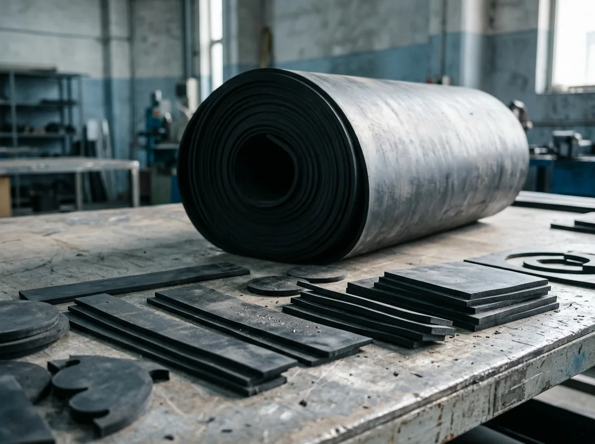
 This image was created with artificial intelligence – marked under Art. 50 of the AI Act, Regulation (EU) 2024/1689. It is a placeholder until the company's photos arrive.
Designing O-ring grooves correctly
Specify O-ring grooves correctly with table, calculation and practical rules For safe sealing and a long service life
O-rings only fulfil their function reliably when the groove geometry is exactly matched to the respective application. Even small deviations in width, depth or tolerance lead to leaks, increased wear or premature failure.
In practice, it repeatedly becomes apparent that it is not the O-ring itself that is the problem, but the design of the groove. Design, production and assembly are directly interlinked here. If the groove is dimensioned incorrectly, leaks, material overload or malfunctions occur – often only under real operating conditions.
A clean design ensures defined compression, stable sealing and a long service life. At the same time, it significantly reduces maintenance effort, downtime and follow-up costs.
Fundamentals of the O-ring groove
Schematic representation (principle)
Cross-section groove + O-ring (simplified):
┌─────────────── Component surface │ ◯ ← O-ring (compressed) │ ┌───────┐ │ │ │ ← Groove │ └───────┘ └─────────────── Mating surface
Compression is created by reduced groove depth in relation to the cord thickness.
Quick decision logic
- Static, pressure < 10 bar → compression 20–30 %, fill level 70–85 %
- Dynamic, linear movement → compression 10–20 %, prioritise lower friction
- High pressure > 50 bar → minimise gap or use a back-up ring
- Soft material (< 70 Shore) → smaller gap, higher extrusion risk
- Temperature/media → allow for swelling, reduce fill level
Design in 4 steps
- Define the application (static/dynamic, pressure, temperature, medium)
- Determine material and hardness
- Select compression and fill level
- Derive groove dimensions and re-check tolerances
Fundamentals of the O-ring groove
The groove serves to accommodate the O-ring in a form-fitting manner and to deform it in a targeted way. This deformation creates the necessary sealing effect.
A distinction is made between:
- static sealing (e.g. flange connections)
- dynamic sealing (e.g. pistons, shafts)
The requirements for the groove differ significantly depending on the application.
Important dimensions of the O-ring groove
In addition to the basic geometry, specific guide values play a central role in practice. The following table shows typical reference values for the design of O-ring grooves in static applications:
| Cord thickness (mm) | Groove depth (mm) | Groove width (mm) | Fill level (%) |
|---|---|---|---|
| 1.5 | approx. 1.2 | approx. 2.0 | 70–85 |
| 2.0 | approx. 1.6 | approx. 2.8 | 70–85 |
| 3.0 | approx. 2.4 | approx. 4.2 | 70–85 |
| 5.0 | approx. 4.0 | approx. 7.0 | 70–85 |
These values serve as a starting point and must be adapted depending on the application, pressure and material.
The fill level describes the ratio between O-ring volume and groove volume and is ideally between 65 and 85 per cent. Higher values lead to overfilling and material stress, lower values to insufficient sealing.
The groove geometry is essentially determined by groove width, groove depth and the transition radius. The groove depth defines the compression of the O-ring and is typically around 15 to 30 per cent in static applications and around 10 to 20 per cent in dynamic applications. Too little compression leads to leaks, while too much compression stresses the material and increases friction and wear.
The groove width must be designed so that the O-ring has sufficient room to deform under pressure. The basic rule here is that the groove volume must be greater than the volume of the O-ring. If this space is not maintained, impermissible squeezing and premature wear occur.
The groove radius, or the design of the edges, plays a role above all for assembly. Sharp edges lead to damage during installation, which is why small radii or chamfers should be provided at all transitions.
Inner and outer sealing
The design differs significantly depending on the installation situation. With inner seals (e.g. pistons), the O-ring is pressed outwards against the cylinder wall, while with outer seals (e.g. shafts) the sealing acts inwards. These differences directly influence compression, tolerances and gap dimension.
With outer seals, the risk of extrusion is generally higher, as the O-ring is pressed more strongly into the gap. Accordingly, tighter gap dimensions or additional back-up elements are required here.
Installation space and gap dimension
The gap dimension directly influences the extrusion risk of the O-ring. Under pressure, the material can be pressed into existing gaps and be damaged in the process.
As pressure increases, the permissible gap decreases. Softer materials are particularly susceptible to extrusion, while harder materials can withstand higher loads.
From certain pressure ranges, the use of back-up rings is required in order to prevent the O-ring from escaping into the gap. This limit depends on material, hardness and temperature and should always be taken into account during design.
Surface requirements
The surface quality of the sealing surfaces has a direct influence on the sealing effect. Surfaces that are too rough lead to leaks, while surfaces that are too smooth can impair the lubricating film.
Typical guide values are in the range of Ra 0.4 to 1.6 µm, depending on application and movement. A matched surface structure ensures stable sealing and reduces wear.
Tolerances and production
Production tolerances have a direct effect on the sealing function.
To be observed:
- dimensional deviations of groove and mating surface
- concentricity and surface quality
- material-related fluctuations
A clean harmonisation of all tolerances prevents functional problems.
Material, temperature and media
The behaviour of the O-ring is strongly influenced by temperature and media. Under the influence of temperature, elastomers change their elasticity and can expand or shrink on contact with media.
These effects have a direct impact on the compression and fill level of the groove. Swelling that is not taken into account can lead to overfilling, while shrinkage causes leaks.
Material and influence on the groove
The behaviour of the O-ring depends strongly on the material used, as elasticity, resilience and resistance to media and temperatures vary. Materials such as NBR are frequently used in standard applications, while FKM is used at high temperatures and under chemical exposure and EPDM is used in particular for water and steam applications.
Depending on the material, the requirements for the groove geometry change. Harder materials require different compression values than softer elastomers, and the swelling behaviour on contact with media must also be taken into account. A matched combination of material and groove is therefore a prerequisite for permanently reliable sealing.
Assembly and lubrication
Fault-free assembly has a direct influence on the function and service life of the seal. Suitable lubrication reduces friction and significantly lowers the risk of installation damage. At the same time, care must be taken to ensure that the O-ring is inserted into the groove without stress and without twisting, as even small deformations can impair the sealing effect.
Damage frequently occurs when sliding over edges or through unsuitable tools. Clean preparation of the components and controlled assembly are therefore essential.
Calculation scheme (repeatable)
Inputs:
- cord thickness d
- desired compression V (%)
- target fill level F (%)
Step 1: Calculate groove depth
- Groove depth = d × (1 − V)
Step 2: Determine groove volume
- O-ring volume ≈ circular area (π × (d/2)²)
- Groove volume = O-ring volume / F
Step 3: Derive groove width
- Groove width = groove volume / groove depth
Step 4: Check gap dimension
- depending on pressure and material → provide back-up ring if necessary
This scheme enables quick and reproducible design.
Practical example
An O-ring with a cord thickness of 3.0 mm is used in a static application. The aim is a compression of around 20 per cent.
The resulting groove depth is around 2.4 mm, while the groove width is selected so that a fill level of around 75 per cent is achieved. In addition, the gap dimension is limited so that no extrusion occurs at operating pressure.
This simple example shows how geometry, material and operating conditions interact.
Comparison with alternatives
O-rings are universal and cost-efficient. For higher requirements, alternatives can be useful:
- X-ring: lower friction, better lubricating film formation in dynamic applications
- Back-up ring combination: prevents extrusion at high pressure
- Flat gasket: suitable for large flange surfaces without dynamic movement
Typical errors in groove design
- Compression too high or too low: an incorrect groove depth leads directly to leaks or excessive material stress.
- Incorrect groove width: too little space prevents the necessary deformation of the O-ring under pressure.
- Unfavourable tolerances: superimposed dimensional deviations change the actual groove geometry and thus the sealing function.
- Failure to take the gap dimension into account: at high pressures, the O-ring can extrude into the gap and be damaged.
- Improper assembly: installation damage often occurs as early as when inserting the O-ring.
Practical recommendations
Typical failure patterns from practice
- Torn edges on the O-ring: missing chamfers or sharp edges
- Shiny, hardened surface: excessive compression and friction
- Seal "frayed" at the sides: extrusion due to excessive gap dimension
- Irregular leakage: tolerance superposition or poor surface
A systematic check of these points significantly reduces failures.
A clean O-ring design is always based on the interaction of all factors:
- application (static or dynamic)
- pressure and temperature
- material of the O-ring
- production capabilities
Calculations should always be supplemented by practical experience and, if necessary, tests.
Frequently asked questions about O-ring grooves
How do I calculate the correct groove depth?
The groove depth results from the cord thickness of the O-ring and the desired compression, typically 10–30 % depending on the application.
Which fill level is optimal?
A fill level between 65 and 85 % ensures sufficient deformation without overfilling the groove.
When is a back-up ring necessary?
At high pressures and larger gap dimensions, a back-up ring is used to prevent extrusion of the O-ring.
What happens with excessive compression?
Excessive compression leads to increased friction, material wear and, in the worst case, premature failure of the seal.
What role does surface roughness play?
Surface roughness directly influences the sealing effect, as surfaces that are too rough cause leaks and surfaces that are too smooth can impair the lubricating film.
What are typical assembly errors with O-rings?
Common errors are twisting, damage from sharp edges and missing lubrication during installation.
Difference between static and dynamic sealing?
Static seals have higher compression, while dynamic applications must take lower friction and wear into account.
Our rubber sheets
For industry and trade, we offer a wide variety of rubber sheets.
SBR rubber sheet
Our high-quality SBR rubber sheet (styrene-butadiene rubber) is the solution for numerous industrial and commercial applications. This rubber sheet is manufactured from first-class styrene-butadiene rubber and is characterised by its outstanding physical properties.
EPDM rubber sheet
Discover the versatility and reliability of our EPDM rubber sheet, which is made from ethylene propylene diene monomer (EPDM). This high-quality elastomer solution has been specially developed to meet the most demanding industrial and commercial applications.
NBR rubber sheet
The NBR rubber sheet is a high-quality industrial product that has been specially developed for applications requiring excellent resistance to oils, greases and various chemicals.
Viton rubber sheet
The Viton rubber sheet is a high-quality technical product that is used for a wide range of industrial applications. Made from fluoro rubber (FKM), it offers outstanding properties that make it the ideal choice for extreme conditions.
FKM rubber sheet
The FKM rubber sheet is a high-quality technical product that is ideal for use in demanding industrial applications. Made from fluoro rubber (FKM), it is characterised by a wide range of outstanding properties that make it the optimal choice for extreme operating conditions.
Silicone rubber sheet
The silicone rubber sheet is a first-class technical product that has been specially developed for applications placing high demands on temperature resistance and flexibility.
PUR rubber sheet
The PUR rubber sheet, made from high-quality polyurethane, is a technically advanced product that has been developed for applications placing the highest demands on abrasion resistance and mechanical load-bearing capacity.
Neoprene rubber sheet
The neoprene rubber sheet, made from high-quality chloroprene rubber (CR), is a versatile technical product that is ideal for a wide range of industrial and commercial applications.