Identifying plastic defects: surface defects, warping and causes in processing
Typical mistakes when processing engineering plastics such as POM, PA or PEEK cost time and quality. Learn how to professionally optimise material selection, storage, machining and bonding.
Engineering plastics such as POM, PA, PEEK, PC or PTFE offer versatile properties and are used in a wide range of industries – from mechanical engineering and medical technology to food processing. However, when machining these high-performance materials in particular, avoidable errors occur time and again that can impair not only quality but also functionality and cost-effectiveness. In this article you will learn which typical processing errors occur, how they affect the end products and which preventive measures you can use to avoid these errors systematically.
Inadequate material selection
A common error in practice is choosing a plastic that is unsuitable for the intended application. Every engineering plastic has specific strengths and weaknesses – for example high temperature resistance, good chemical resistance, sliding properties, insulating properties or dimensional stability. If the wrong material is chosen, this can lead to premature wear, material failure or increased maintenance effort.
How to avoid the error:
- Check the mechanical, thermal, electrical and chemical requirements of the application in detail in advance.
- Use material data sheets, comparison tables and online selection aids.
- If in doubt, consult a materials advisor or application engineer.
- Also take legal requirements and certifications into account (e.g. FDA, EU 10/2011, UL94).
Incorrect storage and material preparation
Many engineering plastics are hygroscopic, i.e. they absorb moisture from the environment. This applies above all to polyamides (PA6, PA66), PET and PC. If moist material is processed, vapour bubbles, stresses or dimensional deviations occur. UV radiation can also lead to embrittlement and yellowing.
How to avoid the error:
- Store plastic semi-finished products in closed, dry rooms and avoid direct sunlight.
- Dry sensitive plastics in accordance with the manufacturer's instructions – usually at 80 to 120 °C for several hours.
- Only process material that has been temperature-conditioned and is free of stress.
- Plan transport and intermediate storage so that no sudden changes in climate occur.
Inadequate tool selection and condition
For high-quality machining, tools with a suitable cutting edge geometry, surface coating and tool life are decisive. If the tools are blunt, unsuitable or worn, chipping, scorch marks, melt burns or burr formation occur.
How to avoid the error:
- Choose tools that are matched to the respective plastic (e.g. positive rake angles, smooth chip chambers).
- Use carbide, PCD or diamond-coated tools for high-strength or abrasive materials.
- Check and change tools regularly as part of a maintenance plan.
- Ensure clean chip evacuation to avoid clogging or frictional heat.
Warpage in plastic – causes and solutions Warpage in plastic components is one of the most common problems in plastics processing. The component unintentionally changes shape after production or during cooling. Particularly with engineering plastic parts, even slight warpage can lead to dimensional deviations, assembly problems or functional faults. The causes of warpage in plastic are usually attributable to stresses within the material or to uneven process conditions.
These errors often arise during processing and only become apparent after demoulding or in later use. Typical causes of warpage in plastic components include uneven wall thicknesses, different cooling rates, material shrinkage, internal stresses in the component and unsuitable tool or process parameters. An unfavourable design or complex geometry can also significantly increase the risk of deformation.
Plastics such as PP, PE or PA in particular are sensitive to shrinkage and thermal stresses. With PP plastics, material orientation during processing can additionally lead to warpage. The component geometry often plays just as great a role as the actual processing settings. A targeted warpage analysis of plastic components helps to systematically narrow down the actual cause. Material properties, temperature profile, tool conditions and design are assessed together. Modern fault analyses of plastic components use measurement data, simulations and practical experience for this purpose.
Several measures have proven effective in avoiding warpage in plastic components. Uniform wall thicknesses should already be taken into account in the design. Controlled cooling, suitable materials and precisely matched processing parameters are equally important. Early analyses and tests also help to reduce stresses in the component and avoid rejects. For demanding applications, the use of dimensionally stable engineering plastics and precise plastic machining is often recommended. This allows warpage, dimensional deviations and subsequent functional problems to be significantly reduced.
Incorrect machining parameters
Engineering plastics are very sensitive to incorrect cutting speeds, excessively high feed rates, insufficient cooling or incorrect infeed values. The result is overheating, thermal welding, uneven surfaces or dimensional inaccuracies.
How to avoid the error:
- Use the machining parameters recommended by the manufacturer as a starting point.
- Reduce the cutting speed for soft or temperature-critical materials.
- Use targeted air or minimum quantity cooling to keep the temperature in the cutting area low.
- Test new materials or machining processes on sample pieces.
Unsuitable clamping technology
An underestimated error lies in incorrect or excessively rigid clamping of the workpiece. Particularly with thermoplastic plastics with low flexural strength or elasticity, this can lead to vibrations, deformation or material fracture.
How to avoid the error:
- Use gentle clamping systems such as vacuum tables, soft jaws or flexible hold-downs.
- Reduce the clamping and contact pressure to the necessary minimum.
- Plan additional supports for long workpieces.
- Check repeat accuracy in series production.
Post-processing without taking stress relief into account
Plastics often contain internal stresses that are released by machining (e.g. milling, drilling). If these stresses are not taken into account, warpage, dimensional deviations or loss of function can occur after machining.
How to avoid the error:
- Allow machined components to rest for a few hours before further work steps are carried out.
- Use tempering processes (e.g. 2–6 hours at 80–150 °C) to reduce stress.
- Take the shrinkage rate of the chosen plastic into account in design and production.
- Use suitable measurement strategies for tight tolerances. Plastic surface defects – typical defect patterns Plastic surface defects impair the appearance, function and quality of components. Even small irregularities can lead to complaints, assembly problems or a shortened service life. Many defects arise during plastics processing and can be identified at an early stage by targeted fault analysis. The most common surface defects in plastics include streaks, bubbles, sink marks, matt areas or stress cracks.
The exact cause depends on the material, processing and ambient conditions. Streaks and flow lines often arise from uneven material flow, temperature differences or moisture in the material. Hygroscopic plastics in particular are sensitive to insufficient drying. Bubbles and air inclusions usually arise from trapped air, residual moisture or excessively high processing temperatures. They weaken the component and have a negative effect on surface quality. Sink marks appear as depressions or uneven areas on the surface.
The cause is often material shrinkage, excessively large wall thicknesses or an insufficient holding pressure phase during processing. Matt or uneven surfaces can be attributable to incorrect tool temperatures, worn tools or unsuitable process parameters. Material batches or contamination also play a role here. Burn marks and discolouration usually arise from overheating or excessively long dwell times of the material. High shear forces and insufficient venting can further promote these defects. Stress cracks and microcracks are among the most critical plastic surface defects. They arise from internal stresses, chemical exposure or mechanical loading and can considerably impair the stability of a component.
A systematic fault analysis of plastic components helps to assess surface defects in a targeted manner and determine their cause. Often, adjusted process parameters, controlled material drying or optimised tool conditions alone lead to significantly better surfaces and higher component quality. Fault analysis of plastic components A systematic fault analysis of plastic components serves to identify quality problems in a targeted manner and determine their cause unambiguously. Particularly with engineering plastics, visible damage alone is often not enough to identify the actual trigger of a problem. For this reason, material, processing and operating conditions are considered together.
Typical defect patterns in plastic components are warpage, surface defects, cracking, dimensional deviations or premature wear. The causes can already arise in the design, occur during processing or only become visible in later use.
A central component of plastic fault analysis is the assessment of material properties. Materials differ significantly with regard to moisture absorption, temperature resistance, shrinkage and mechanical load capacity. If these properties are insufficiently taken into account during material selection, the risk of functional faults and quality problems increases.
Processing conditions also play a major role. Errors in temperature control, cooling, tool design or material drying often lead to stresses, deformation or surface defects. Particularly with hygroscopic plastics such as PC or PA, even increased residual moisture can considerably influence component quality.
Professional fault analysis of plastic components includes various testing and assessment procedures. These include visual inspections, dimensional checks, material analyses, load tests and the examination of temperature and process data. In many cases, simulations or microscopic examinations additionally support the cause analysis.
A structured fault analysis provides more than a mere damage assessment. It creates the basis for improving processes, reducing rejects and achieving stable component quality in the long term. Particularly in industrial applications, early analysis helps to avoid production downtime and cost-intensive complaints.
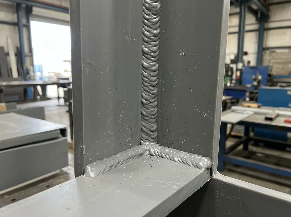
Incorrect bolting or bonding
Not all plastics can be bonded or bolted equally well. If incorrect adhesives, excessively high tightening torques or unsuitable designs are used, cracks, permanent deformation or a defective joint can occur.
How to avoid the error:
- Check the bonding and joining suitability of the chosen plastic in advance.
- Use certified bonding and joining systems for critical applications (e.g. primer, 2K adhesive, structural adhesive).
- For bolted joints, ensure adapted thread forms, support sleeves and controlled tightening.
- Include expansion compensation in the design for thermal loading.
Conclusion
The processing of engineering plastics is more complex than it appears at first glance. Errors often arise through lack of knowledge, time pressure or insufficient experience. Anyone who deals intensively with material properties and knows typical pitfalls can rule out many problems from the outset. In this way, reject rates can be reduced, rework avoided and product quality improved sustainably.
Frequently asked questions (FAQ)
Which plastics must be dried before processing? Polyamides (PA6, PA66), PET, PBT and PC are hygroscopic and should definitely be dried before processing, as otherwise vapour bubbles, porosities or warpage can occur.
What must be taken into account when CNC machining POM? POM can be machined very well, but tends to form burrs and to stress relaxation. Sharp tools, suitable feed rates and clean chip evacuation are important in order to avoid heat.
Why does a plastic component warp after milling? The cause usually lies in internal stresses that are discharged by the removal of material. Intermediate storage, targeted tempering and observance of the machining sequence help to minimise this effect.
How do I recognise incorrect machining parameters? Typical signs are scorch marks, burr formation, score marks, irregular surfaces or even melting. In such cases, feed rate, cutting speed and cooling should be checked.