Anisotropy in plastics – what designers need to consider
What anisotropy in plastics means, what effects it has and how designers allow for the direction-dependent behaviour.
Anisotropy is one of the decisive influencing variables in materials engineering. Particularly in engineering plastics, fibre-reinforced materials and formed metals, it directly shapes real component behaviour. Designs that are assessed computationally using idealised, isotropic characteristic values frequently show clear differences between the longitudinal and transverse directions under real loads.
Direction-dependent properties influence load-bearing capacity, distortion, dimensional accuracy, thermal expansion, fatigue strength and typical damage mechanisms. Systematic consideration of anisotropic effects enables robust, durable and economically optimised solutions.
This technical article brings together materials-physics fundamentals, quantitative characteristic values, practical damage patterns, manufacturing influences, simulation approaches, standards and concrete recommendations for design and material selection.
What does anisotropy mean?
Anisotropy describes direction-dependent material properties. A material is considered anisotropic as soon as mechanical, thermal or physical characteristic values differ from one another along different spatial directions.
Typical direction-dependent properties are:
- tensile strength
- compressive strength
- modulus of elasticity (E modulus)
- shear modulus
- impact strength
- coefficient of thermal expansion
- electrical conductivity
- shrinkage
In contrast to this are isotropic materials with direction-independent behaviour.
Materials-physics background
Anisotropy arises from a preferential internal structural orientation. This can be molecular, crystalline or fibre-related. In plastics, polymer chains align along the flow direction during the flow process in injection moulding. In fibre-reinforced materials, glass or carbon fibres preferentially orient along these flow paths. In semi-crystalline thermoplastics, directed crystallisation additionally influences the subsequent mechanical behaviour. Temperature gradients during cooling can moreover generate residual stresses that further reinforce the direction-dependent behaviour.
Metals also exhibit anisotropic properties. Rolling processes stretch grains in the microstructure and align them along the rolling direction. Drawing processes lead to comparable texture formation. These structural changes have a direct effect on the stress-strain behaviour and lead to different yield points, strengths or formabilities depending on the load direction.
Mathematically, anisotropy is described by direction-dependent material tensors. In linear elasticity theory there are up to 21 independent stiffness constants. For engineering applications, simplified models are frequently used, such as orthotropic materials with three principal axes or transversely isotropic materials with one preferred axis. These models form the basis for realistic FEM calculations.
Quantitative differences in real materials
The extent of anisotropic properties is clearly evident in numerical values.
Example PA-GF30 (injection moulding)
- tensile strength parallel to the flow direction: 150–200 MPa
- tensile strength transverse: 90–120 MPa
- E modulus parallel: 8,000–10,000 MPa
- E modulus transverse: 5,000–6,500 MPa
Strength differences of 30–50 % are not an exception.
Example extruded POM
- E modulus in the extrusion direction: approx. 3,000 MPa
- E modulus transverse: approx. 2,700 MPa
- shrinkage longitudinal/transverse: measurably different
Example aluminium sheet (rolled)
- yield point in the rolling direction higher than transverse
- different formability depending on direction
These differences are essential for the design of safety-relevant components.
Effects of anisotropy on component behaviour
- Load-bearing capacity: The main load direction defines the usable strength. A misorientation considerably reduces safety reserves, particularly with localised loads or notches.
- Distortion: Different shrinkage values generate internal stresses. The result is deflection, torsion or dimensional deviations outside permissible tolerances.
- Thermal behaviour: Differing coefficients of thermal expansion lead to superimposed stresses under temperature cycling. In bolted or hybrid constructions, this increases susceptibility to cracking.
- Fatigue strength: Direction-dependent fatigue significantly influences service life. Cyclic transverse loads considerably reduce fatigue strength.
Typical defect patterns
Cracking transverse to the orientation
Stress cracks form preferentially along weaker directions. In fibre composites, matrix failure is frequently observed.
Delamination
Multi-layer composites can become detached under transverse loading.
Distortion after mechanical machining
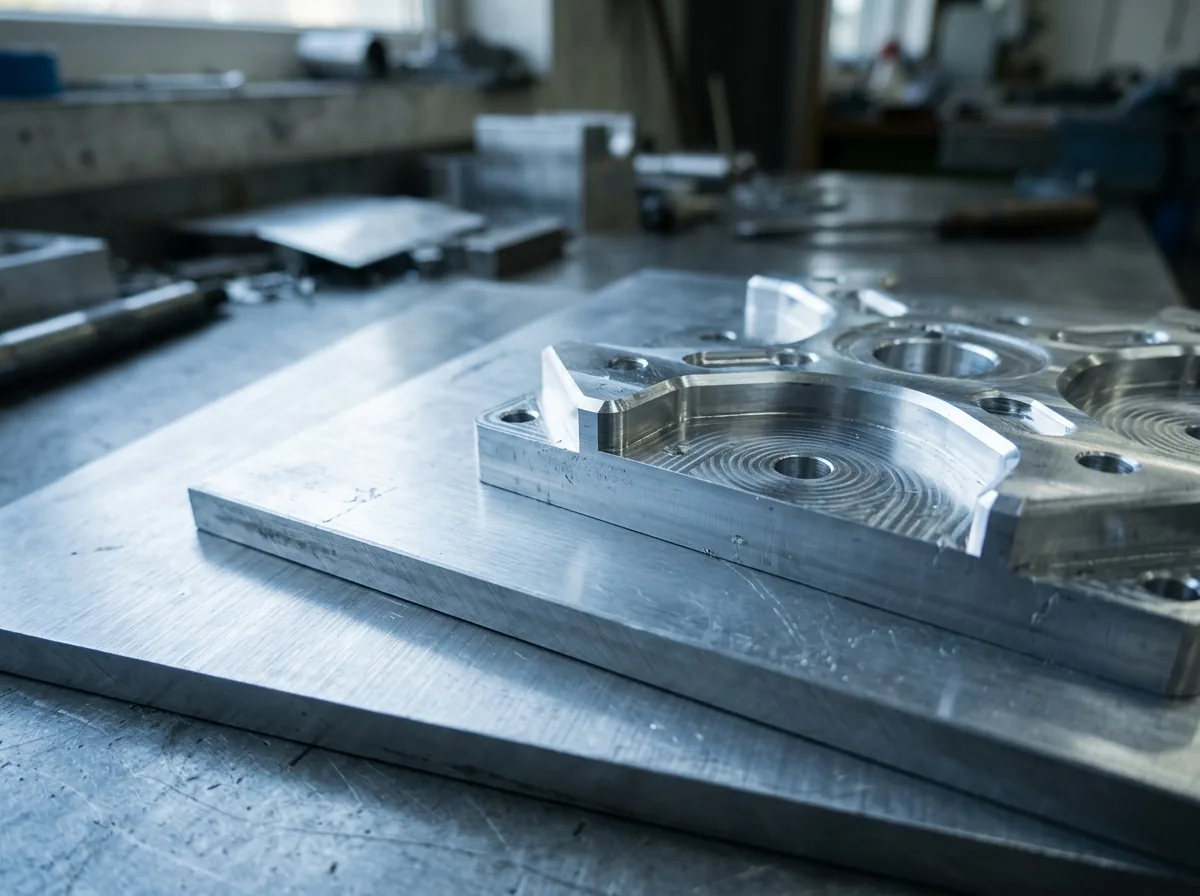
Milling or facing processes release residual stresses. Semi-finished products subsequently change their geometry.
Screw failure
Bores transverse to the preferred direction exhibit increased notch sensitivity. Screw preloads can lead to radial cracks.
Comparison of manufacturing processes
Injection moulding produces a complex, locally varying fibre and molecular orientation. Edge zones frequently exhibit a high orientation along the flow direction, while lower or even deflecting structures may occur in the core region. As a result, the anisotropic behaviour varies within a single component.
Extrusion, by contrast, produces a distinctly pronounced main orientation along the extrusion axis. The directional behaviour is generally more homogeneous and more constant across the cross-section than in injection-moulded components.
Laminating and pressing processes enable targeted definition of fibre layers. Through the controlled layer build-up, load directions can be deliberately optimised, which is used in particular in lightweight construction. The respective manufacturing process thus decisively determines the subsequent mechanical performance.
Simulation of anisotropic materials
For a realistic FEM calculation, the following are required:
- orthotropic material definition
- direction-dependent elastic and shear moduli
- definition of the principal axes
- coupling with injection moulding simulation to transfer fibre orientation
Modern CAE systems enable the integration of real orientation data into structural analysis.
Practical case: failure due to transverse loading
A PA-GF30 holder showed cracking in the area of a bolted connection after a short operating time. The main force acted transverse to the flow direction of the injection-moulded component. In this direction, the tensile strength was considerably below the value in the longitudinal direction. In addition, the bore reinforced the notch effect, while the screw preload generated local stress peaks.
The combination of reduced transverse strength, notch geometry and preload led to premature failure. By adapting the tool design with an optimised flow direction and a design modification of the load path, the stress could be shifted into the stronger material direction. As a result, the component service life increased significantly.
Standards and test methods
Direction-dependent characteristic values are determined using standardised test methods:
- DIN EN ISO 527 – tensile test
- DIN EN ISO 178 – flexural test
- DIN EN ISO 179 / 180 – impact strength
Test specimens are taken specifically parallel and perpendicular to the flow direction.
Relevant materials with pronounced anisotropy
- glass-fibre-reinforced polyamide (PA-GF)
- PBT-GF
- PP-GF
- CF-reinforced high-performance materials
- extruded POM
- PE-HD
- rolled aluminium sheets
Design guide
- align the main load along the stronger material direction
- assess transverse loading separately
- minimise notch effects
- position screw points in a load-optimised way
- take residual stresses into account during machining
- use simulation for safety-relevant components
Anisotropic or isotropic – selection criteria
| Application | Isotropic suitable | Anisotropic suitable |
|---|---|---|
| uniform loading | ✓ | |
| defined main load | ✓ | |
| lightweight optimisation | ✓ | |
| high-precision dimensional parts | ✓ |
Summary
Anisotropy describes direction-dependent material properties. A material is considered anisotropic as soon as mechanical, thermal or physical characteristic values take on different values depending on the load direction.
Manufacturing processes, fibre content, molecular orientation and microstructure determine the extent of anisotropic effects. These manifest themselves in load-bearing capacity, distortion, thermal behaviour, fatigue and fatigue strength.
A well-founded design analyses load direction, manufacturing process and real operating conditions holistically. This results in calculable, safe and economically optimised components.
FAQ on anisotropy
What does anisotropic mean in simple terms? An anisotropic material has different properties depending on direction.
Why do fibre-reinforced plastics exhibit strongly anisotropic behaviour? Fibres align along the flow direction and create a preferred mechanical axis.
How large are the differences typically? Strength differences of 30–50 % between the longitudinal and transverse directions are usual in fibre-reinforced plastics.
How is anisotropy taken into account in FEM? Via orthotropic material models with direction-dependent elastic and shear moduli.
Which materials exhibit particularly strong anisotropy? Fibre-reinforced plastics, extruded semi-finished products and rolled metals exhibit pronounced direction dependence.