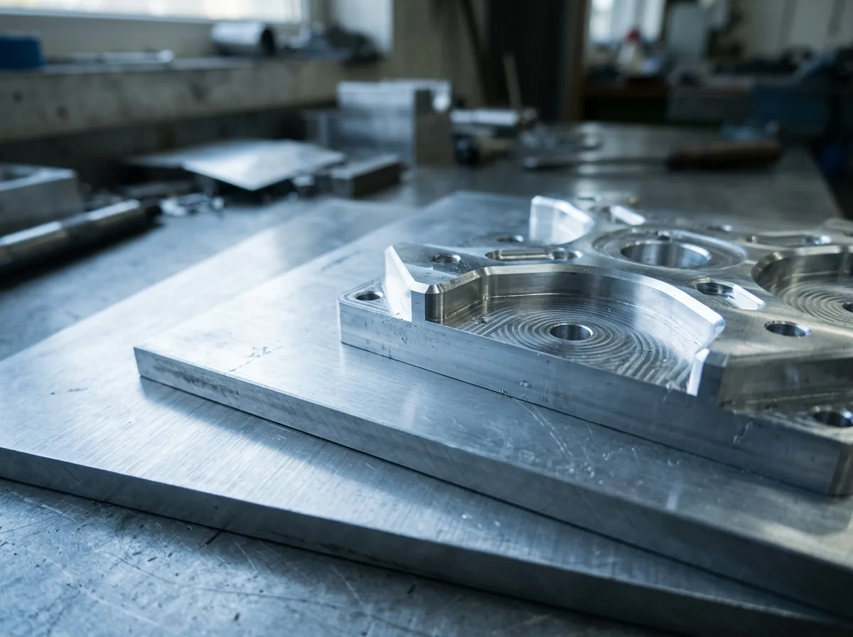
 This image was created with artificial intelligence – marked under Art. 50 of the AI Act, Regulation (EU) 2024/1689. It is a placeholder until the company's photos arrive.
Effects of heat and temperature changes on aluminium sheets
How do heat and temperature changes affect aluminium sheets? Expansion, stresses and material behaviour explained clearly.
Aluminium sheets react strongly to temperature changes. The ability to conduct heat quickly, the high thermal expansion and the temperature-dependent mechanical properties make this material particularly sensitive to heat, cold and rapid load changes. For structures, machine parts or technical components, it is crucial to plan for these effects at an early stage in order to avoid deformation, malfunctions or failures.
Thermal behaviour of aluminium
Due to its metallic bonding structure, aluminium reacts particularly strongly to temperature changes. The atoms in the microstructure have comparatively high mobility; even a small input of heat leads to clearly detectable lattice expansion, which manifests in the form of changes in length, stress shifts and dimensional deviations. At the same time, heat spreads very quickly throughout the entire component, as aluminium is among the most thermally conductive of all engineering metals. Although this rapid temperature equalisation ensures efficient dissipation of local heat, it also means that components can hardly maintain areas of stable temperature.
Characteristic of aluminium is the relatively high coefficient of thermal expansion of around 23–24 µm/(m·K). This means that even small temperature changes produce measurable changes in length, which can add up to several tenths of a millimetre or even millimetres in the case of large-format sheets. If, for example, a 1.5 m long sheet is heated by 50 K, it already grows by around 1.7 mm in calculation. This property is particularly relevant for precision applications such as machine guides, mounting surfaces or housing elements, where dimensional accuracy under load must be guaranteed without fail.
As temperature rises, the mechanical properties of aluminium also change significantly. The yield strength falls, the material becomes softer and reacts more sensitively to mechanical stress. The modulus of elasticity also decreases, so that components yield more at warmer temperatures. This effect becomes noticeable from around 80 °C and intensifies with increasing temperature. Under continuous load above 120 °C, creep deformation can occur, i.e. a slow plastic deformation under sustained stress.
The thermal conductivity of aluminium is in the range of 200–235 W/m·K and thus significantly above that of steel. This leads to rapid temperature changes throughout the entire component, particularly when localised heat sources such as motors, power electronics or process heat occur. Temperature differences within the sheet – for example between the top and bottom or between thick and thin areas – generate internal stresses that can manifest in the form of dishing, deflection or local deformation.
Temperature profiles by application type
- Mechanical engineering: Housing temperatures mostly 40–80 °C; heating from motors, hydraulics, pumps and control units; locally high heat in the vicinity of drives; distortion of large base plates due to temperature gradients.
- Electronics & power engineering: Hotspots up to 100–120 °C directly at the component; strong temperature gradient between component and carrier plate; rapid changes during switching on and off; risk of local bulging and contact problems.
- Outdoor applications: Ambient temperatures from -20 to +60 °C; strong day/night cycles; rapid cooling by wind or rain; high residual stresses due to uneven surface heating.
- Vehicle construction: Temperatures near the engine and exhaust 80–150 °C; additional winter loads in the sub-zero range; rapid thermal cycles in traffic jam and driving operation; material fatigue due to repeated load cycles.
Effects of high temperatures
Aluminium loses not only stiffness but also structural stability at rising temperatures. With increasing exposure to heat, the metallic bonds in the microstructure begin to loosen. As a result, atoms can shift against one another more easily, which leads directly to a softer and less dimensionally stable material. This process begins at moderate temperatures in the range of 60–80 °C and continues as temperature rises. Above around 100 °C, the yield strength decreases significantly, and the component reacts increasingly sensitively to external loads.
The combination of temperature and mechanical load is particularly challenging. While a pure increase in temperature can already lead to deformation, external forces massively amplify this effect. Fits become tighter or looser, long sheets begin to bulge and sealing surfaces lose their flatness. In applications where components are exposed to elevated temperature for many hours or months – for example in machines, electronics assembly or vehicle construction – these effects occur not only in the short term but continuously and cumulatively.
A further problem is uneven temperature distribution. If individual areas are heated faster than others, internal stress fields arise. Massive zones store heat for longer, while thin areas cool more quickly. These differences lead to deformation that can already be functionally relevant in the tenth-of-a-millimetre range. Especially in precise assemblies, such thermal distortion can already be sufficient to block movements or produce defects.
Why does creep deformation occur?
Creep deformation is a slow but steady plastic change in the material under a constant load and simultaneously elevated temperature. Aluminium exhibits this behaviour at temperatures that are well below its melting point. Physically, creep occurs because atoms can move more easily along certain lattice planes when heated. Under a sustained mechanical load, they gradually migrate in the direction of the load – the material "flows", as it were.
It is crucial that creep deformation does not have to be immediately visible. It can occur over weeks, months or even years and initially cause only minimal changes. A bolted connection gradually loses preload force, a sheet slowly bends or a precisely aligned surface loses its flatness. Creep is particularly critical under continuous loads, such as those occurring in machine frames, base plates, housings or electronic assemblies. The higher the temperature and the longer the load acts, the stronger and more irreversible the deformation.
With temperature + load, atoms move permanently in the direction of the applied force. As a result, plastic deformations occur that do not recover.
Temperature changes and thermal shock
Temperature changes generate particularly high stresses, as different areas of the component heat up or cool down at different rates.
What happens physically?
- the warm zone expands,
- the cold zone remains rigid,
- an internal stress gradient arises,
- the material attempts to compensate for the unequal expansions and deforms.
Complex geometries (pockets, milled recesses, thin webs) amplify this effect.
CNC machining and temperature-related stress behaviour
The thermal effects that influence aluminium sheets in operation often begin during CNC machining. With every milling or drilling operation, frictional heat is generated, which initially develops locally at the tool cutting edge and then transfers into the material. Aluminium conducts this heat very quickly, but not evenly: areas with greater mass store the heat for longer, thin zones release it more quickly. This creates different temperature fields within the same sheet.
These local temperature differences lead to internal stresses that dissipate unevenly as the sheet cools. If, for example, only one side is heavily machined or heated more strongly, this side contracts differently on cooling than the opposite side. The result can be visible and measurable dishing. Internal stresses that were already present in the starting material are also partly released or redistributed during machining, which can lead to distortion or dimensional deviations after production.
A further influencing factor is heat generation during longer machining times. If cooling is interrupted, if the tool is blunt or if too high a cutting speed is selected, the temperature of the sheet rises locally. During further milling, the temperature zone shifts, causing the material to react differently and stresses to build up. After unclamping the sheet, these stresses can discharge abruptly and lead to distortion or dimensional changes.
CNC-optimised machining is one of the most important factors in preventing subsequent distortion under temperature.
Table: Thermal CNC effects and typical distortion
| Cause | Thermal effect | Typical distortion | Note |
|---|---|---|---|
| One-sided depth of cut | asymmetrical heating | 0.3–0.8 mm | especially with large sheets |
| High cutting speed | local overheating | dimensional deviations up to 0.2 mm | thin walls critical |
| Interrupted cooling | uneven cooling | dishing | especially during milling pauses |
| Incorrect clamping technique | heat accumulates | distortion in the edge area | clamping jaws distribute |
FEM validation in thermal applications
FEM analyses are crucial in order to make thermal risks visible already during planning. A valid simulation covers both the temperature field and the resulting mechanical stresses.
Important validation steps:
- comparison of the simulation with real temperature measurements,
- verification of the boundary conditions (convection, conductivity, contact heat),
- comparison of symmetrical and asymmetrical load cases,
- sensitivity analyses for thickness, material, mounting points.
FEM validation reduces design errors because critical zones become visible before production.
Thermal fault diagnosis in operation
Thermal problems often only occur during use. A structured diagnosis saves time and prevents consequential damage.
Typical diagnostic methods:
- thermal imaging to identify hotspots,
- measurement of flatness before and after temperature loading,
- observation of bolted connections (loss of preload force),
- analysis of noises or vibrations as an indication of internal stresses.
Common signs of thermal faults:
- uneven bulging,
- migrating components or fits,
- unexplained sealing problems,
- loose screws despite correct assembly.
Systematic fault diagnosis helps to realistically assess the actual thermal behaviour of a system and to derive suitable measures.
Assembly errors under thermal load
Many problems arise only after an aluminium sheet has been installed and not during production. The typical thermal effects – expansion, stress, dishing and loss of preload force – become particularly evident when the assembly restricts the natural mobility of the material. One of the most common causes is over-constrained bolting. If a sheet is rigidly fixed at too many points at the same time, it cannot compensate for its temperature-related expansion. The result is growing stress fields within the material, which manifest externally in the form of dishing, edge cracks or changes in fits. Some assemblies begin to jam or components migrate out of their positions because the sheet tries to "work itself free".
A further effect is the loss of preload in bolted connections. Aluminium expands more than steel screws. As soon as the temperature rises, the aluminium expands more than the screw, as a result of which the preload force falls. The connection thus becomes increasingly loose, even if it was originally tightened correctly. If vibrations or cyclic loads are added, this process accelerates. For this reason, thermally loaded connections require design measures such as disc springs, spring steel washers or sliding points that can partially compensate for the loss of force.
Sealing surfaces are also susceptible to thermal assembly errors. If a sheet bulges when heated or if screws yield due to temperature-related expansion, the seal loses its even compression. At the same time, many sealing materials can shrink or lose flexibility on cooling. The interaction of these effects means that previously tight assemblies can become leaky – even if the assembly was formally correct. Only an assembly that takes temperature movements into account and allows the material defined freedom of movement prevents this type of fault in the long term.
Additional calculation examples
For engineers, it is helpful to know not only the linear expansion but also the change in area, the distortion moment and the loss of screw force.
1. Linear expansion in two directions (2D)
A sheet measures 800 × 600 mm. Temperature rise: 45 K.
ΔL_x = 23 · 0.8 · 45 = 828 µm ΔL_y = 23 · 0.6 · 45 = 621 µm
The area grows by around 0.5–0.7 mm in each direction.
2. Bending due to temperature gradient
Sheet: 12 mm thickness, ΔT between top and bottom = 30 K.
M_th ≈ E · α · t² · ΔT / 12 ≈ 70,000 MPa · 23e-6 · (12 mm)² · 30 / 12 ≈ 0.5–0.8 Nm/mm
Result: slight but measurable bulging.
3. Loss of screw force due to different expansion
Aluminium sheet + steel screw M8. ΔT = 60 K.
Aluminium expands more:
- ΔL_Alu = 23 µm/mK,
- ΔL_Steel = 12 µm/mK.
Difference over 20 mm sheet thickness → preload force falls by 10–18 %.
4. Distortion after asymmetrical milling
One-sided pocket 3 mm deep in a 600 × 400 × 10 mm sheet:
- stress arises due to unequal wall thicknesses,
- distortion up to 0.3–0.8 mm is usual.
Symmetrical milling halves this effect.
Selecting the right alloy
Choosing the right alloy is one of the decisive steps in reliably designing aluminium sheets for thermally loaded applications. Every alloy has a specific combination of microstructure, strength, temperature behaviour and corrosion resistance. These properties determine how stable a sheet behaves under heat, how much its mechanical properties change and how well it withstands repeated temperature changes.
Alloys such as EN AW 5083 are among the most thermally stable variants. They contain magnesium as the main constituent, which gives a very good combination of strength, ductility and temperature resistance. The sheet retains its structural integrity even when heated to around 120 °C and distorts less than softer or more strongly hardenable alloys. For massive base plates, frames, machine components and precision mounts, 5083 is therefore often the first choice.
EN AW 6082 offers higher strength than 5083, but remains temperature-stable enough for dynamic or varying loads. Due to the mixture of magnesium and silicon, this alloy shows a good response to cyclic thermal loads. It is suitable for components that are both mechanically demanding and operate in environments where repeated heating and cooling occur. In machine and plant construction, 6082 is a frequently used all-round alloy.
For applications in the moderate temperature range, EN AW 5754 is a solid, versatile choice. This alloy is less strong than 5083 or 6082 but has a stable structure and good corrosion resistance. It is frequently used in housings, covers or outdoor areas where temperature movements do occur but no extreme peaks are reached.
It is crucial that the choice of alloy is not considered in isolation. It directly influences the dimensional accuracy, the settling behaviour, the service life and the long-term stability of a structure. The higher the thermal load and the more dynamic the temperature profiles, the more stable and low-stress the selected alloy should be.
Practical examples
- Mechanical engineering: A 2000 × 1200 × 20 mm base plate heats up locally to 70 °C and as a result dishes by 0.4–0.7 mm. Precision guides subsequently no longer run parallel.
- Electronics: A heat sink heats one area of the sheet to around 110 °C, while the remaining area stays at around 40 °C. The resulting bulging leads to fit problems and impairs the flatness of the mounting surface.
- Vehicle engineering: Repeated temperature cycles between -15 and +90 °C cause a creeping loss of preload force in bolted connections. After a few months, components loosen despite correct initial assembly.
Calculating expansion
In addition to ΔL, designers should also consider 2D expansion:
ΔA ≈ 2 · α · A₀ · ΔT
As a result, the area increases noticeably, which becomes relevant for cover plates or housing fronts.
Bending moment due to temperature gradient
M_th ≈ E · α · t² · ΔT / 12
The thicker the sheet, the lower the bending effect – but the higher the stress force.
In conclusion
Thermally loaded aluminium sheets place high demands on planning, design and production. The combination of high thermal expansion, pronounced thermal conductivity and temperature-dependent mechanical properties makes it necessary to take all relevant influencing factors into account already during the development phase. If these aspects are incorporated into the design at an early stage, distortion, local overloads, material fatigue and malfunctions can be reliably avoided.
Overall, it is clear that careful thermal design is not an add-on but a fundamental quality factor. It increases operational safety, extends service life and prevents costly rework – especially in the case of large-format or precision-critical aluminium components.
Taking temperature load into account correctly: Get advice on the right aluminium sheet or configure your cut directly online – tailored to real operating conditions.
FAQ
How much does aluminium expand? Around 23–24 µm/m·K – thus significantly more than steel. Even small temperature changes cause measurable changes in length, which can quickly add up to several millimetres in the case of large sheets.
Which alloy is best suited? 5083 and 6082 are the most stable options for thermal loads, as they remain dimensionally stable even at higher temperatures and exhibit lower losses of strength.
How do I prevent distortion? Through sliding points, symmetrical designs, even heating, adapted machining strategies and low-stress alloys. Avoiding over-constrained bolting is also crucial.
What happens with rapid temperature changes? High stresses arise within the material, which can lead to microcracks, local bulging or permanent dimensional deviations – especially with complex geometries.
Why do bolted connections lose preload force when hot? Because aluminium expands more than steel screws. As a result, the preload force is reduced, which can lead to loosening and vibration problems in the long term.
How do I recognise thermally induced damage at an early stage? Typical indications are uneven bulging, migrating fits, fluctuating flatness, sealing problems or the loosening of bolted connections. Thermal images provide additional clarity about hotspots.
What role does component thickness play in thermal effects? Thick sheets distort less but store heat for longer and build up higher stresses. Thin sheets react more quickly but are more susceptible to visible distortion.
What is the advantage of low-stress cast plates? Cast plates (e.g. G.AL, MIC6) have minimal internal stresses and are therefore particularly stable with respect to temperature changes and CNC machining.